

MTPA and Manual Phase Angle Sweeping
The quest for maximum energy efficiency in electric motor control often revolves around Maximum Torque Per Ampere (MTPA). This operating point ensures the motor produces the highest possible torque (Te) for a given current magnitude (Is) , minimising copper losses and maximising battery range in applications like Electric Vehicles (EVs).
Defining Key Terms and Concepts
Motor control is simplified using the dq -axis reference frame (or rotor flux reference frame), which rotates synchronously with the rotor’s permanent magnets (for Permanent Magnet Synchronous Motors, PMSMs).
- The d-axis (Direct) aligns with the rotor’s magnetic flux. Current in this axis, id, primarily affects the magnetising field.
- The q-axis (Quadrature) is perpendicular to the d-axis. Current in this axis, iq, is primarily responsible for torque generation.
- Back-EMF (Eb) is the voltage induced in the motor windings due to the spinning magnets (Faraday’s Law), which opposes the applied voltage. In the dq-frame, the back-EMF is typically aligned with the q-axis, Eq ≈ ωeλpm, where ωe is the electrical speed and λpm is the permanent magnet flux linkage.
The Importance of Phase Angle Sweeping
The phase angle (γ) defines the vector relationship between the total stator current (Is) and the d and q components Is forms an angle γ with the q axis). For a given current magnitude, the angle γ must be optimised to find the (id, iq) combination that maximises torque.
Manual phase angle sweeping involves systematically fixing the total current magnitude and incrementally adjusting the current vector angle while measuring the resulting torque. The angle that yields the peak torque for that specific current magnitude is the MTPA point. This is crucial for accurate motor characterisation as it accounts for complex, real-world effects like magnetic saturation, which computer models struggle to predict precisely.
The generalised torque equation for an Interior Permanent Magnet Synchronous Motor, PMSM (IPMSM) is:
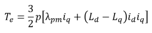
Where p is the number of pole pairs, λpm is the flux of the permanent magnet, and Ld, Lq are the inductances. The terms represent the magnet torque and the reluctance torque, respectively.
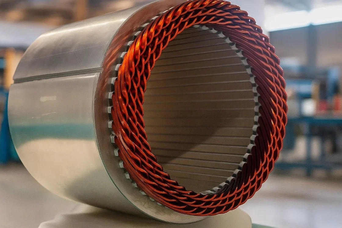
Manual Phase Sweeping helps calibrate Control Algorithms like Field Oriented Control (FOC) (in the case of the PMSM being tested at iNetic, see Figure 1), which generally rely on pre-determined MTPA look-up tables providing a more robust range to sweep for MTPA. It was observed that software generated MPTA tables are accurate i.e. from MotorCAD below field weakening region but are unable to effectively determine them for starting currents during field weakening regions, hence the need for manual phase sweeping.
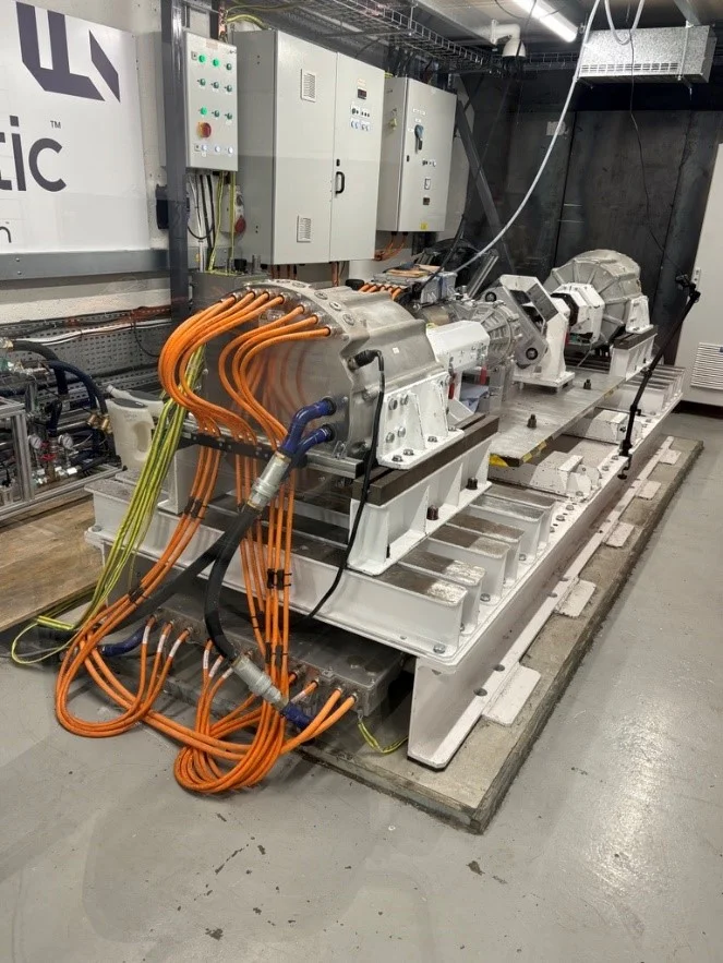
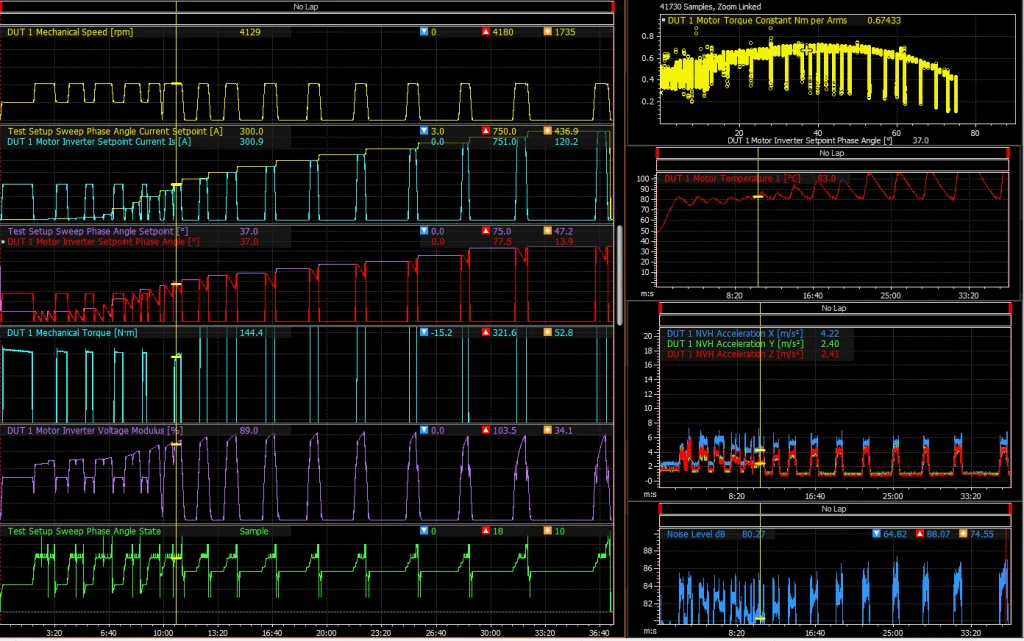
Figure 2 illustrates how data is collected, presented and interpreted via MOTEC I2 Pro, a software capturing Controller Area Network (CAN) bus data during a Phase Angle Sweep. We are generally interested in understanding the variation in Torque are the Phase Angle is Swept at different Currents, keeping an eye on the Voltage Modulus to ensure we are achieving Maximum Torque whilst maintaining efficiency. A host of additional data, for example, Noise, Vibration, Temperature, Flow rates, help the controller perform additional data analysis and develop robust Fault Control procedures.
Challenges
The main challenge of manual sweeping is that it is time-consuming and temperature-dependent. Motor parameters like resistance and inductance (Ld, Lq) and strength of the permanent magnet change with temperature and magnetic saturation, making a one-time test insufficient for full characterisation. The process requires precise control and measurement equipment (dynamometers and high-resolution sensors), and was comprehensively tested at iNetic.
Issues with high motor speeds in field weakening or maximum torque per voltage regions requires MTPA logic to transition seamlessly, which requires careful manual calibration of tables when calibrating the inverter look-up tables to ensure current stability and to avoid loss of control.
Despite the difficulty, manual sweeping provides the core data to create the MTPA lookup tables used by motor controllers, ensuring peak efficiency and performance across the entire operating range for traction electric motor applications.
Conclusion
Optimising the performance of an electrical machine across its entire speed range is an essential procedure for traction electric motor development. It helps ensure system efficiency and that the inverter is calibrated to effectively provide an accurate response to the end user’s torque response. Testing such electrical machines with robust, well developed rig setups, like that shown in Figure 1 become crucial in providing confidence in the end product for customers.