

What Does "Traction-Ready" Actually Mean?
The phrase “traction-ready” gets used a lot in the electric drivetrain space. OEM procurement teams hear it from suppliers pitching motors, inverters and integrated e-axles. But what does it actually mean in engineering terms — and how do you verify it?
The honest answer is that traction-ready is not a single test or a single certificate. It is the outcome of a structured validation programme that takes a drivetrain from raw material qualification all the way through to full system testing under real-world vehicle load conditions. Done properly, it is the process by which a supplier demonstrates not just that a product works, but that it will keep working reliably in service — across temperature extremes, voltage transients, millions of duty cycles and the full range of edge cases your application will eventually throw at it.
UK EV manufacturing is growing fast. According to SMMT figures, UK output of battery electric, plug-in hybrid and hybrid vehicles rose to nearly 299,000 units in 2025 — a record 41.7% share of total output, even as overall UK production fell. Gigafactories are coming online at Sunderland and Bridgwater. The DRIVE35 programme has committed £2.5 billion through to 2035 to zero-emission vehicle manufacturing and supply chain development. All of that creates real demand for rigorous, locally available EV component and powertrain validation — and shortens the feedback loop when design, manufacture and testing sit under the same roof.
This article walks through each stage of a typical EV drivetrain validation programme, from material qualification to full e-axle system testing, and explains what is being verified, why it matters and what the common failure modes are at each stage.
What Is an E-Axle (EDU)?
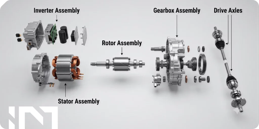
Before getting into testing, it is worth clarifying terms, because the industry uses several interchangeably.
An electric drive unit (EDU) — often called an e-axle — is an integrated assembly combining three main elements: the traction motor, the power electronics (traction inverter) and the mechanical reduction (gearbox or reducer), all in a single compact package. It replaces the internal combustion engine and conventional multi-component driveline.
The move toward integrated e-axles is driven by packaging efficiency, reduced interface complexity and the system-level optimisation that becomes possible when motor, inverter and transmission are developed together rather than independently. Modern production e-axles routinely operate at speeds well above 15,000 rpm, at voltages of 400 V to 800 V, and must deliver this over a service life measured in hundreds of thousands of kilometres.
That performance and reliability envelope is exactly what a traction validation programme is designed to prove.
How EV Powertrain Validation Is Structured
A well-run EV drivetrain validation programme follows the V-model logic: requirements are defined at the top left, detailed design flows down the left-hand side, and each level of testing on the right-hand side verifies the corresponding design level. You do not just run a system test at the end and hope for the best; you validate at every level, catching issues early when they are cheap to fix.
The Design Verification Plan and Report (DVP&R) maps every design requirement to a specific test, defines the pass/fail criteria, and records the result. Alongside it sits the Design Failure Mode and Effects Analysis (DFMEA), which identifies what could fail, why, how severe the consequence is and what the testing programme needs to catch. For safety-related functions, ISO 26262 functional safety requirements drive the level of analysis and verification rigour, with ASIL ratings running from A (lowest) to D (highest).
A complete powertrain validation programme covers performance and efficiency, thermal behaviour, mechanical durability, electromagnetic compatibility (EMC), environmental robustness and abuse. What follows is how that maps to the physical test stages.
Material and Lamination Qualification
A traction motor’s magnetic circuit is built from a stack of thin electrical-steel laminations — typically 0.25 mm to 0.35 mm thick — separated by an interlaminar insulation coating. Their job is to carry the magnetic flux while minimising energy loss. Getting the material right is foundational; no amount of downstream testing can compensate for out-of-specification steel.
- Core loss and permeability are measured using an Epstein test frame (per IEC 60404-2) or single-sheet testers. Core loss — the sum of hysteresis loss and eddy-current loss — directly determines motor efficiency. Laminations that exceed the specified core loss will produce a motor that runs hotter and less efficiently than the design predicts.
- Interlaminar resistance testing (ASTM A937) verifies the integrity of the insulation coating between laminations. Shorted laminations allow eddy currents to flow across the stack rather than being contained within individual sheets, dramatically increasing core loss.
- Permanent magnet characterisation — B–H curves, coercivity and the knee point of the demagnetisation curve — is critical for PMSMs. A magnet with a higher-than-expected knee point is at risk of irreversible demagnetisation if the motor is pushed into field-weakening operation at elevated temperature.
- Dimensional metrology runs in parallel throughout. At iNetic, this is supported by a dedicated metrology suite including digital shadowgraph, height measurement equipment, 3D measurement capability for shafts and rotors using TESA instrumentation, and tensile testing for mechanical property verification.
| Standard(s) | iNetic equipment |
|---|---|
| IEC 60404-2, ASTM A937 | TESA metrology suite, digital shadowgraph, tensile tester |
Component-Level Testing
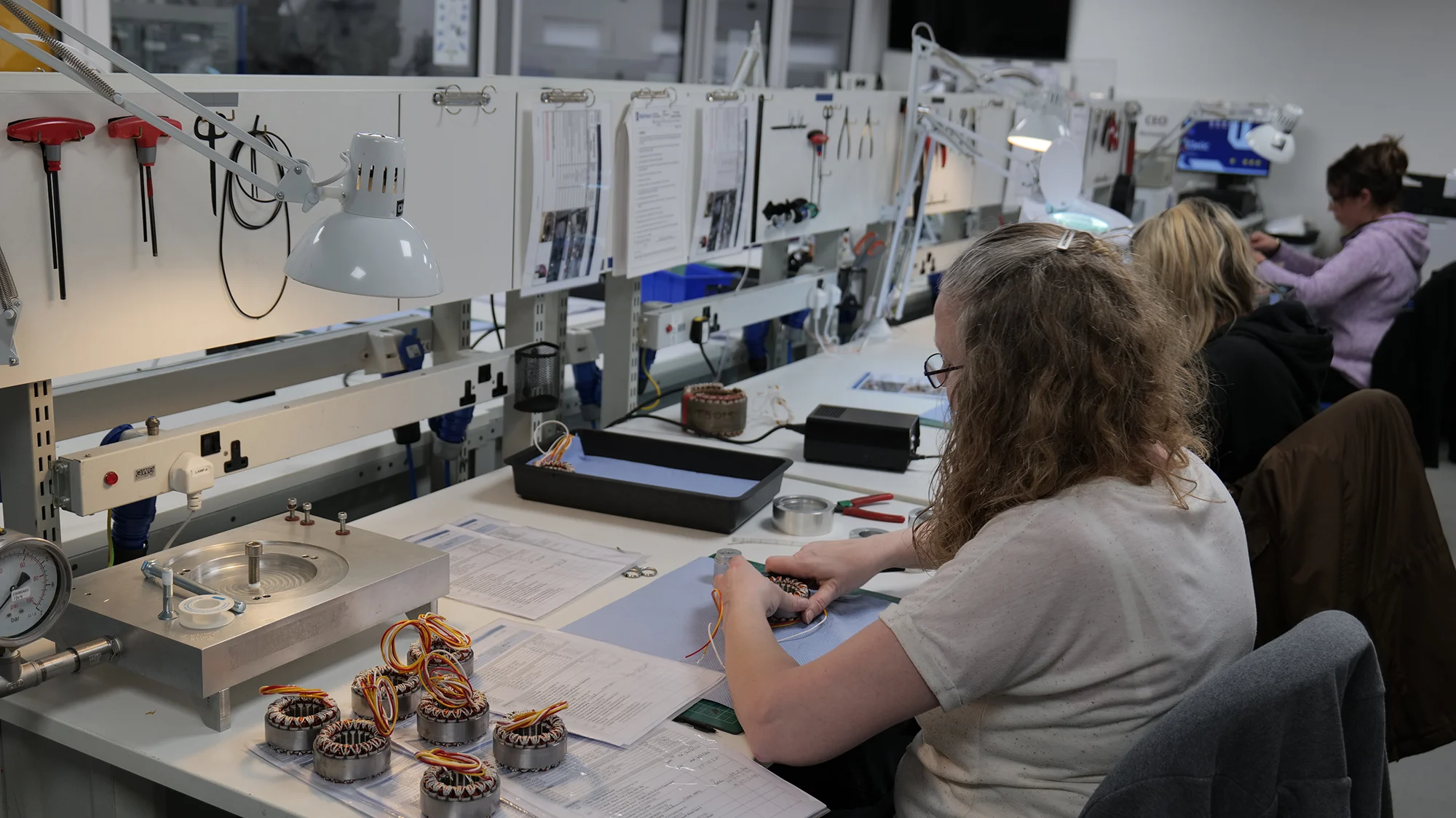
With materials qualified, individual components are validated before assembly into a system. This stage catches manufacturing-process defects and design-margin issues at the lowest cost point.
- Winding and insulation testing covers insulation resistance, hi-pot and surge testing. Surge testing is particularly important for hairpin stator windings — the style increasingly used in traction motors — because the fast-switching transients from a SiC inverter place high repetitive voltage stress on the inter-turn insulation.
- Bearing validation addresses one of the EV-specific failure modes: bearing currents. The common-mode voltage output from a PWM inverter induces shaft voltages that can discharge through the bearings in a process called electrostatic discharge machining (EDM), creating pitting and fluting on bearing raceways. Mitigation strategies — insulated bearings, hybrid ceramic bearings, shaft grounding rings — are validated at this stage.
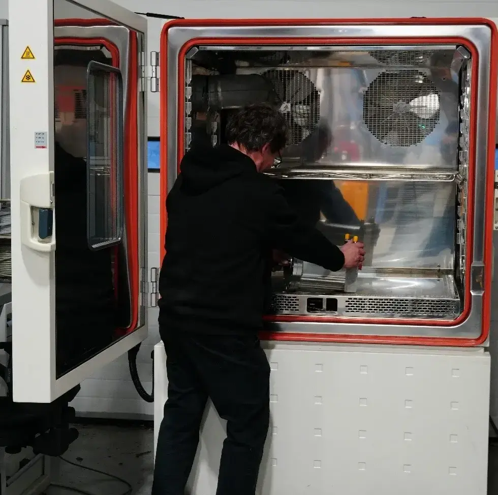
- Environmental testing is applied throughout component development. iNetic operates five thermal chambers covering −42°C to 180°C with a controlled ramp rate of 4°C/min, enabling thermal cycling, cold-soak and elevated-temperature soak tests that reveal failures driven by differential thermal expansion, moisture ingress or lubricant degradation.
| Standard(s) | iNetic equipment |
|---|---|
| ISO 16750, IEC 60068 | 5× thermal chambers (−42°C to 180°C, 4°C/min), metrology suite |
Motor Dynamometer Testing
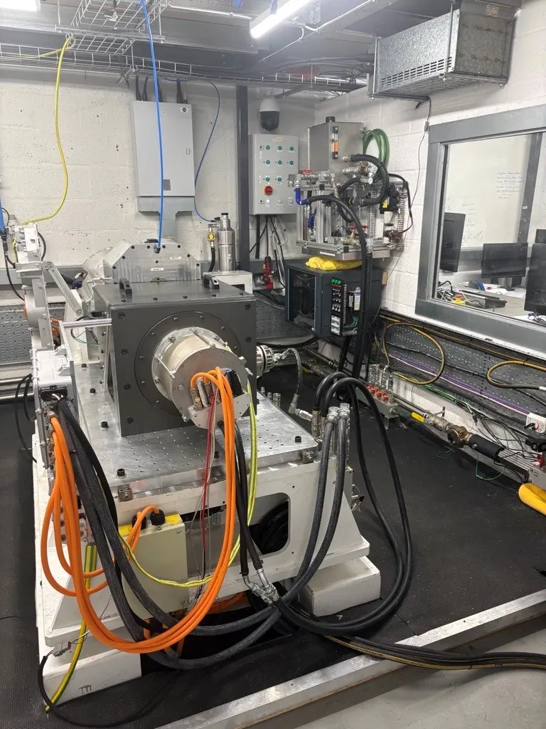
Motor dynamometer testing is where the bulk of performance characterisation and thermal validation takes place, and the most direct answer to: does this motor do what the model said it would?
- Back-to-back dynamometer configuration shares the DC bus between the drive and load machines, recirculating energy within the cell rather than dissipating it. This allows sustained high-power testing at a fraction of the electrical energy cost, and is essential for long thermal endurance tests at representative power levels.
- iNetic Multi-Speed Dynamometer: back-to-back, 350 kW, 800 V maximum, DC bus recirculating up to 600 A, battery emulator supply, water cooling (up to 80°C) and oil cooling (up to 100°C, 8 bar).
- iNetic High-Power Dynamometer Platform: 350 kW, 3,500 Nm, 7.2:1 gearbox, max DUT speed 21,000 rpm, vehicle emulation, unmanned running, dual-voltage operation up to 1,000 V.
- Compact Low Power Testing Platforms: 30 kW, back-to-back, 800 V, air-cooled — for motor development and efficiency characterisation at prototype stage.
Key tests include efficiency mapping (torque–speed–efficiency grid across the full operating envelope), thermal and derating characterisation, and NVH assessment of torque ripple, cogging and electromagnetic force orders.
| Standard(s) | iNetic equipment |
|---|---|
| ISO 21782-2, ISO 21782-3 | Multi-Speed Dyno (350 kW), High-Power Platform (21kRPM), Compact 30 kW rig |
Inverter and Power Electronics Testing
The traction inverter converts battery DC to variable-frequency AC, controlling motor torque and speed. It switches at frequencies of 5 kHz to 20 kHz, handles very high currents, and must do so across temperatures from −40°C cold-start to over 100°C junction temperature at peak load.
- Precision power analysis uses PPA1500 power analysers to measure input DC and output AC power simultaneously across the full operating range, with the bandwidth needed to capture high-frequency content from SiC-switched waveforms accurately.
- Regenerative load testing returns energy back through the DC bus rather than dissipating it — critical for sustained high-power test runs.
- Double pulse testing characterises the switching behaviour of power semiconductors: a controlled gate pulse sequence generates measured turn-on and turn-off energy, feeding into loss models and thermal design validation.
- EMC testing at component level follows CISPR 25, covering conducted and radiated emissions from 150 kHz to 2.5 GHz. The high switching frequencies of SiC-based inverters make EMC a design challenge, not an afterthought.
The trend toward 800 V architectures and silicon carbide (SiC) switching devices raises the bar across all of these tests — higher voltages demand better isolation; faster switching edges require higher-bandwidth instrumentation.
| Standard(s) | iNetic equipment |
|---|---|
| CISPR 25, ISO 26262, ISO 21782-3 | Electronics test system, PPA1500 analysers, regenerative load, data acquisition |
Full EDU / E-Axle System Testing
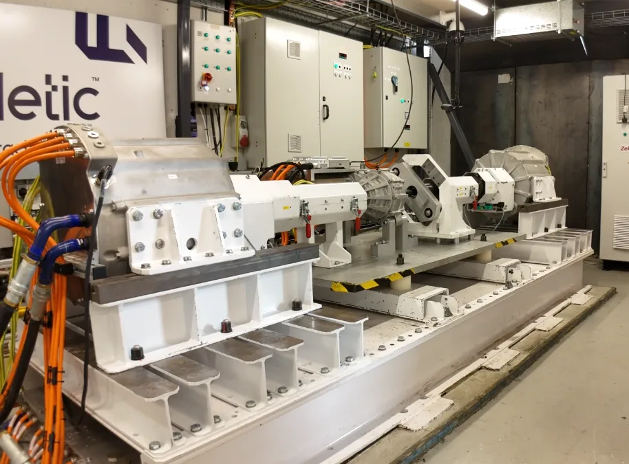
System-level testing is where everything comes together. The motor, inverter and transmission are tested as an integrated unit under conditions that represent real-world vehicle operation as closely as possible.
- iNetic E-Axle Dynamometer Platform: twin-dyno wheel-speed rig, 3,500 Nm and 350 kW per dyno, 1,000 V DC capability with 600 A recirculating, 100 kWth of combined cooling. A high-power DC/DC converter enables isolation between the dyno DC bus and the DUT DC bus, giving precise control over simulated battery voltage independently of load condition.The critical point about system testing is that it reveals behaviours that simply cannot be predicted by testing components in isolation. Thermal interactions between motor and inverter, gearbox efficiency losses under load, NVH content driven by combined gear mesh and electromagnetic force orders, and control algorithm behaviour across the full torque–speed range — all emerge only at system level.
- Vehicle emulation uses a real-time vehicle model to simulate road load, inertia, grade and drive cycle. The EDU is driven through WLTP, NEDC or application-specific duty cycles, including regenerative braking events. Peak performance events — full-throttle acceleration, sustained hill climbing, panic-brake regeneration — are reproducible on demand.
- Durability and endurance testing runs the complete EDU through accumulated mileage equivalent cycles, thermal cycling, and load cycling that reproduces the fatigue spectrum of real-world usage.
| Standard(s) | iNetic equipment |
|---|---|
| ISO 21782-5/6, CISPR 25, UNECE R85, R10 | E-Axle Dyno Platform (2× 350 kW dyno, 1000 V, 100 kWth cooling) |
Key Standards and Frameworks
For engineering leads navigating the standards landscape, the core framework for EV powertrain testing in the UK and EU is as follows:
| Standard | Scope |
|---|---|
| ISO 21782 (Parts 1–7) | Test spec for electric propulsion components — motor performance, inverter, DC/DC, durability |
| ISO 26262 | Functional safety — ASIL A–D, HARA, DFMEA, FMEDA for safety-critical traction functions |
| ISO 16750 (Parts 1–5) | Environmental conditions — climatic, mechanical (vibration/shock), electrical transients |
| CISPR 25 | Component-level EMC emissions (150 kHz – 2.5 GHz) |
| CISPR 12 / CISPR 36 | Vehicle-level electromagnetic emissions |
| UNECE R85 | Net power and 30-minute maximum power of electric drive systems |
| UNECE R10 (ECE R10) | Vehicle EMC type approval for the European market |
Design, Manufacture and Test Under One Roof
A traction validation programme is not just a sequence of tests. It is a feedback loop. When issues emerge — as they always do — the speed at which the root cause is understood and a design change is implemented determines how efficiently development proceeds.
That feedback loop is shortest when the team that designed the motor, the team that manufactured it and the team running the test are working together in the same facility, with access to the same data. When testing is outsourced to a remote test house, the loop is slower, the context is lost in translation and iteration cycles extend.
iNetic Traction’s validation capability spans the full programme described here — from incoming material metrology through component testing, motor dyno characterisation, inverter electronics validation and full e-axle system testing with vehicle emulation — alongside in-house motor design and manufacture. For OEM engineering leads evaluating a drivetrain supply partner, that integration is a meaningful de-risker.
Conclusion
“Traction-ready” means a drivetrain that has been systematically proven, at every level from raw material to complete system, to meet its performance, efficiency, thermal, mechanical, electrical and safety requirements. It is not a claim that can be made on the basis of a simulation model and a few bench tests.
It requires a structured validation programme that follows the logic of the V-model, references the appropriate standards, and uses test equipment capable of the measurement fidelity that modern EV drivetrains demand. For UK OEMs building electrified vehicles, the growth in domestic EV production means that rigorous validation no longer requires shipping hardware overseas. The capability is here.
