

Sizing Electric Motors and Batteries for a Municipal Sweeper: A 4.8-Tonne Case Study
How tractive-force modeling, auxiliary power budgeting, and motor selection actually size an electric sweeper’s battery and drivetrain.
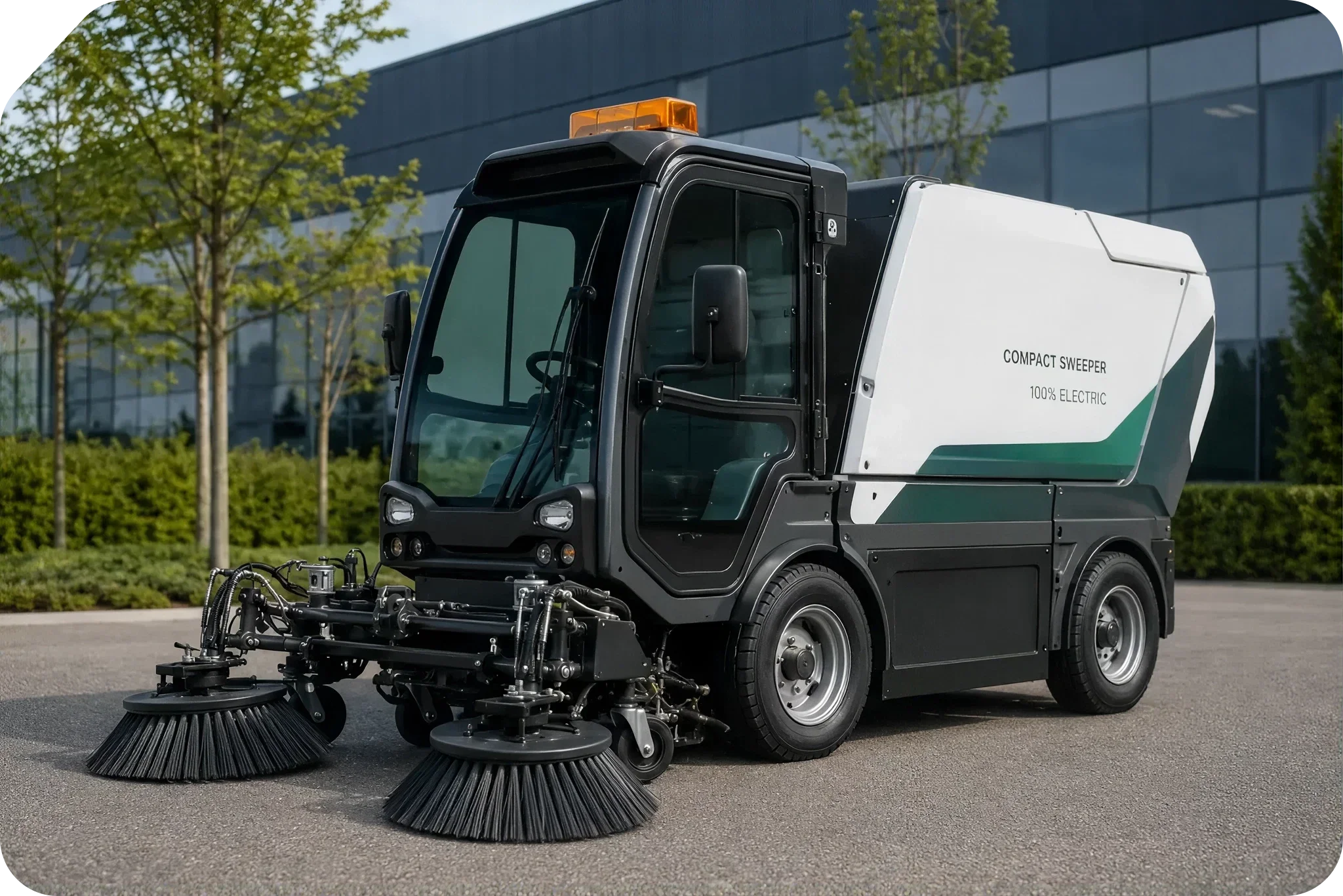
Executive Summary
Electrifying a municipal sweeper is a different problem than electrifying a passenger car. A sweeper has to drive itself down the road and run a vacuum turbine, a hydraulic pump, and a water system at the same time — often at low speed, for hours, without a break. That combined load is what actually sizes the battery and motors, not top speed.
This case study works through the complete power budget for a 4.8-tonne compact electric sweeper: tractive forces at highway speed and on a 30% grade, auxiliary loads from the suction fan and hydraulic aggregate, the battery sizing math those loads drive, and the motor and inverter hardware that covers both jobs. The traction motor tops out around 88 kW to cover the worst-case grade climb. The auxiliary side runs on two permanent-magnet motor families supplied by iNetic Traction — the iEV and sEV lines — sized for continuous duty rather than peak torque, since a hydraulic pump on a sweeper runs for hours, not seconds.
Two battery configurations cover the expected duty cycles: a 63 kWh baseline pack and a 100 kWh extended pack, both built on a 335V nominal architecture. A centralized vehicle control unit — the EVParts xCU — replaces the mechanical power take-off network entirely, handling motor control, thermal management, and safety interlocks from a single dual-core safety microprocessor.The base platform carries over from the diesel version largely unchanged: a two-part ladder-frame chassis, articulated hydraulic steering, independent front suspension, and a Torsen self-locking differential. What changes is everything downstream of the engine bay — a lithium-ion battery, a traction drive motor, a suction fan drive, and an electro-hydraulic power pack take the place of the diesel engine and its belt-driven PTO.
Vehicle Architecture Overview
| Technical Parameter | Specification / Baseline | Operational Context |
|---|---|---|
| Gross Vehicle Weight (GVW) | 4,800 kg (4.8 t) | Maximum permissible laden weight |
| Maximum Operational Payload | 2100 kg | Material, debris, and fluid payload capacity |
| Vehicle Unladen Mass | 2700 kg | Net weight excluding payload and water reserves |
| Debris Hopper Capacity | 2.0 m³ | Fabricated from 1.4003 stainless steel |
| Total Water Tank System | 425 L (275 L fresh / 150 L service) | Dual-circuit dust suppression supply |
| Maximum Travel Speed | 50 km/h (13.89 m/s) | On-road transit between municipal depots |
| Operational Sweeping Speed | 0–15 km/h (avg. 8 km/h) | Active working velocity range |
| Maximum Gradeability | 30% incline | Hill-climbing performance at full payload |
| Nominal High-Voltage Bus | 335 V (approx. 250–450 V operating window) | System DC distribution voltage range |
| Operational Noise Level | 92 dB(A) external pass-by | Low-noise urban operation certification |
Switching from a hydrostatic transmission to a direct electric architecture eliminates local tailpipe emissions, cuts structural noise, and lets the vehicle throttle each subsystem independently instead of running one engine at a fixed speed for everything. Hitting an 8-to-10-hour shift on a single charge comes down to getting three things right: the tractive-force model, the auxiliary power budget, and the motor selection. The rest of this case study works through each.
System Power, Mechanical Forces, and Energy Requirements
Sizing a sweeper’s powertrain means modeling two separate operating regimes: Transport Mode, which needs high speed and no auxiliary power, and Sweeping Mode, which runs at low speed but under continuous, heavy auxiliary load. Transport Mode sets the top-end power and torque; Sweeping Mode sets the energy budget.
Tractive Force Dynamics and Mechanical Power Modeling
The total tractive force required at the drive wheels is the sum of four components: rolling resistance, aerodynamic drag, gradient resistance, and acceleration force.
F_total = F_r + F_ad + F_grad + F_acc
Each term is defined as:
F_ad = 0.5 · ρ · Cd · A · v² (aerodynamic drag)
F_r = f_r · m · g · cos(θ) (rolling resistance)
F_acc = m · a · (1 + γ) (acceleration force, incl. rotational inertia)
F_grad = m · g · sin(θ) (gradient / grade force)
For this 4.8-tonne platform, the working parameters are:
- m = 4,800 kg (gross vehicle weight)
- g = 9.81 m/s² (standard gravity)
- f_r = 0.018 (rolling resistance coefficient — commercial heavy-duty tires on urban asphalt)
- ρ = 1.225 kg/m³ (ambient air density, standard conditions)
- Cd = 0.65 (aerodynamic drag coefficient for a compact utility cab)
- A = 4.0 m² (effective frontal area)
- v = vehicle velocity (m/s)
- θ = road gradient angle (radians)
- γ = 0.08 (rotational inertia factor for wheel, axle, and motor assembly)
Scenario A: Transport Mode at Top Speed (50 km/h, Level Surface)
On flat terrain, with θ = 0° and a = 0 m/s²:
F_r = 0.018 · 4,800 kg · 9.81 m/s² · 1.0 = 847.58 N
F_ad = 0.5 · 1.225 kg/m³ · 0.65 · 4.0 m² · (13.89 m/s)² = 307.20 N
F_total_transit = 847.58 N + 307.20 N = 1,154.78 N
Wheel power demand:
P_wheel_transit = F_total_transit · v = 1,154.78 N · 13.89 m/s = 16.04 kW
With a driveline efficiency η_driveline = 0.88, the electrical power drawn by the traction motor is:
P_motor_transit = P_wheel_transit / η_driveline = 16.04 / 0.88 = 18.23 kW
Scenario B: Maximum Gradeability Limit (30% Grade at 15 km/h)
A 30% grade corresponds to a road angle θ = arctan(0.30) ≈ 0.2915 rad (16.7°), giving sin(θ) = 0.2873 and cos(θ) = 0.9578.
F_r = 0.018 · 4,800 kg · 9.81 m/s² · 0.9578 = 811.81 N
F_grad = 4,800 kg · 9.81 m/s² · 0.2873 = 13,528.47 N
F_ad = 0.5 · 1.225 kg/m³ · 0.65 · 4.0 m² · (4.17 m/s)² = 27.68 N
F_total_grade = 811.81 N + 13,528.47 N + 27.68 N = 14,367.96 N
P_wheel_grade = 14,367.96 N · 4.17 m/s = 59.91 kW
P_motor_grade = P_wheel_grade / η_driveline = 59.91 / 0.88 = 68.08 kW
That number lines up with the 88 kW peak traction motor actually specified on the platform, leaving real margin for transient acceleration while climbing a steep urban ramp — the motor isn’t running at its ceiling just to make the grade spec.
Auxiliary Subsystem Power Characterization
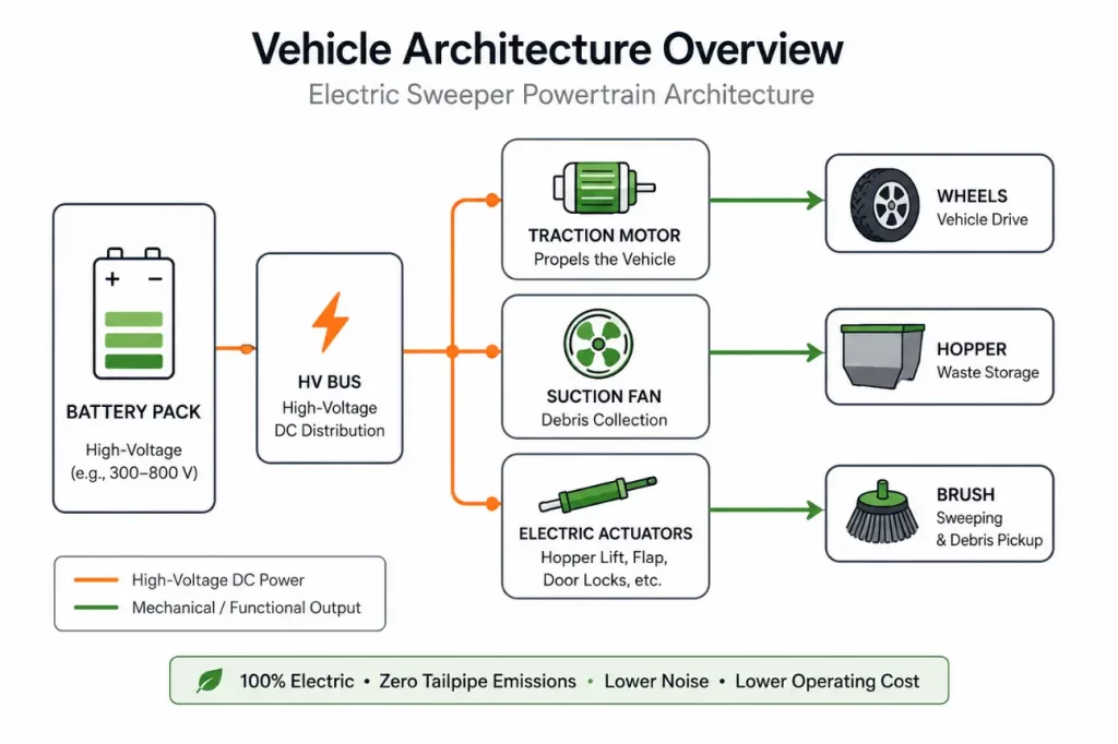
During active sweeping (0–15 km/h, averaging 8 km/h), tractive power drops off, but three auxiliary loads take over as the dominant draw:
- Suction fan drive: the vacuum turbine that pulls debris through the intake nozzle, hose, and hopper screen. Continuous draw: 8.5 kW.
- Electro-hydraulic aggregate: powers steering actuators, brush lift/tilt linkages, brush rotation motors (0–120 rpm), the third-brush extension mechanism, hopper dump cylinders, and water spray pumps. Peak mechanical rating: 12.0 kW; continuous duty-cycle average: 6.5 kW.
- Low-voltage auxiliaries and cabin HVAC: touch display, armrest controller, LED work lights, water recirculation pumps, and climate control. Continuous draw: 1.2 kW.
| Operating Regime | Traction Motor | Suction Fan | Hydraulic Aggregate | LV / HVAC | Total Net Power |
|---|---|---|---|---|---|
| High-Speed Transit (50 km/h) | 18.23 kW | 0.00 kW | 0.90 kW (steering only, electrical) | 0.80 kW | 19.93 kW |
| Nominal Sweeping (8 km/h, flat) | 2.20 kW | 9.52 kW | 7.28 kW | 1.20 kW | 20.20 kW |
| Heavy-Duty Sweeping (full load) | 4.10 kW | 9.52 kW | 13.44 kW | 1.50 kW | 28.56 kW |
| Peak Grade Incline (30% at 15 km/h) | 68.08 kW | 0.00 kW | 1.68 kW | 0.80 kW | 70.56 kW |
* Suction Fan and Hydraulic Aggregate figures in this table are electrical draw at the battery, not the mechanical shaft-power ratings quoted above (8.5 kW and 6.5-12.0 kW respectively) — each is divided by the inverter and motor efficiency (η_inv · η_mot ≈ 0.89) used elsewhere in this case study to convert shaft output into the electrical load the pack actually sees.
Electro-Hydraulic Subsystem Sizing and Motor Selection
Decoupling the hydraulic and vacuum systems from the traction line, and driving each with its own permanent-magnet motor, is what makes demand-based power control possible in the first place. The alternative — one engine and a belt-driven PTO — can’t throttle one subsystem without affecting the others. iNetic Traction supplies the motor hardware for this platform, and its lineup covers both ends of the requirement:
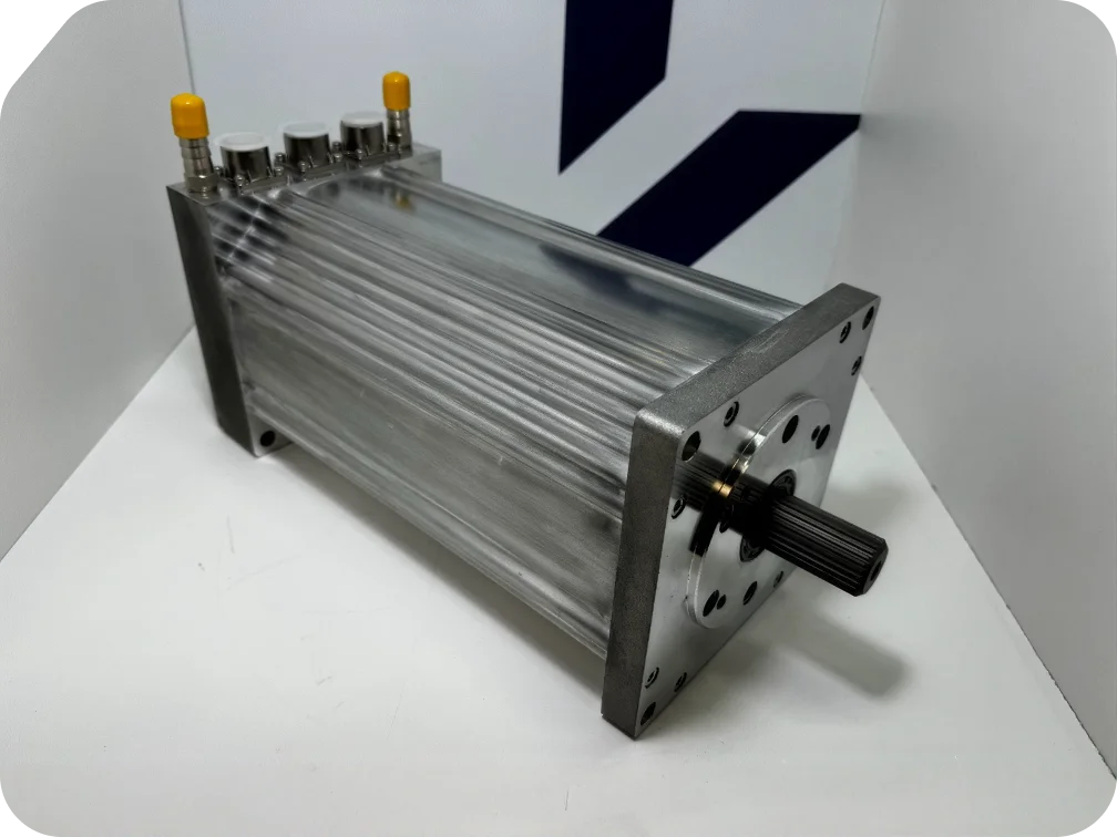
- iEV Motor Series (iEV-2U-WN400 & iEV-4U-WN400, paired with the A4001 inverter): heavy-duty, liquid-cooled radial-flux motors built for direct pump coupling and continuous industrial duty.
- sEV Motor Series (e.g., sEV135-3U): compact, air-cooled PMSM motors spanning a wide voltage range (12–650 VDC), suited to lower-power fans, blowers, and auxiliary pumps.
Motor and Inverter Technical Specification Matrix
The iEV configuration uses 3-phase radial-flux permanent-magnet motors with internal resolvers for closed-loop vector control, PT1000 temperature sensors, 50:50 water-glycol liquid cooling, and IP67 connectors. The sEV series is the air-cooled alternative for space- and weight-constrained mounts.
| Specification | Unit | sEV135-3U | iEV-2U-WN400 + A4001 | iEV-4U-WN400 + A4001 | Relevance |
|---|---|---|---|---|---|
| DC Operating Voltage Range | VDC | 12–650 (96 V nominal, this application) | ≈250–450* | ≈250–450* | Direct connection to vehicle DC bus |
| Max Phase Current | Arms | 200 | 410 | 410 | High transient current capacity |
| Continuous Drive Power | kW | up to 12.0 | 150 (inverter @ 400V) / 32 (motor) | 150 (inverter @ 400V) / 33 (motor) | Subsystem continuous rating limit |
| Inverter Switching Frequency | kHz | External inverter dependent | 10 | 10 | Smooth vector field modulation |
| Motor Peak Torque (10 s rating) | Nm | 30 | 150 | 325 | Dynamic breakaway load capacity |
| Motor Peak Power (10 s rating) | kW | 10 | 47 | 48 | Dynamic burst power capacity |
| Motor Continuous Torque | Nm | 15 | 87 | 148 | Sustained mechanical shaft load |
| Motor Continuous Power | kW | 2.7 | 32 | 33 | Continuous thermal electrical draw |
| Peak Torque Density | Nm/kg (Nm/L) | 1.8 (34) | — (4.7) | — (57.0) | Power and mass density comparison |
| Maximum Operational Speed | rpm | 6,000 | 4,000 | 4,000 | High-speed fan & pump shaft speed |
| Bare Motor Mass (excl. cables) | kg | 17 | 32 | 54 | 15 kg / 46.8% lighter (sEV vs iEV-2U) |
| Cross-Section Profile | mm | 140 × 140 | 180 × 180 | 180 × 180 | Compact packaging envelope |
| Package Length (excl. shaft) | mm | 234 | 256 | 381 | Axial space optimization |
| Permissible Shaft Loads | N | 100 axial / 200 radial | 100 axial / 200 radial | 100 axial / 200 radial | Direct pump/fan coupling support |
| Stator Winding Thermal Limits | °C | 165 (derate) / 180 (max) | 165 (derate) / 180 (max) | 165 (derate) / 180 (max) | Thermal protection safety threshold |
| Cooling Method | — | Air / fan cooled | Water-glycol 50:50 | Water-glycol 50:50 | Flexible thermal architecture |
| Ingress Protection Rating | — | IP67 | IP67 | IP67 | Rugged washdown & dust resistance |
* The DC operating voltage range for the iEV-2U/4U + A4001 pairing is shown as it appears in the source documentation (“250 –”); the upper bound was not legible in the source material and is estimated here from the battery’s known operating window (260–385 VDC) plus margin. Flagged for vendor datasheet confirmation.
Component Selection and Drive Matching Analysis
Picking the actual motor-inverter pairing comes down to matching the torque-speed curve to the job, then checking mass, envelope, and thermal margin.
Electro-Hydraulic Aggregate Drive Selection
The hydraulic aggregate needs 12.0 kW of continuous mechanical power at 2,500 rpm pump speed. The required shaft torque at that point:
T_hyd = P/ω = 12,000 W / (2π·2,500/60 rad/s) = 12,000 / 261.80 = 45.84 Nm
- iEV-2U-WN400: 87 Nm continuous torque, 33 kW continuous shaft power at 2,500 rpm. Running at 45.84 Nm puts it at a 52.7% continuous load factor — inside its efficiency island, with 150 Nm peak (10 s rating) in reserve for cold-start viscosity spikes.
- iEV-4U-WN400: 148 Nm continuous torque, 43 kW continuous power. Functionally capable, but oversized for this job — an extra 22 kg of mass and 125 mm of axial length the pump bay doesn’t have room for.
The iEV-2U-WN400 paired with the A4001 inverter is the better fit for the hydraulic aggregate.
Suction Turbine Fan Drive Selection
The suction fan needs 8.5 kW continuous at 3,200 rpm. Shaft torque:
T_fan = P/ω = 8,500 W / (2π·3,200/60 rad/s) = 8,500 / 335.10 = 25.37 Nm
- iEV-2U-WN400 (liquid-cooled): at 25.37 Nm and 3,200 rpm, the motor uses less than 30% of its 87 Nm continuous rating — enough margin to spin the fan from rest to full speed in under two seconds without tripping thermal limits. It also drops straight into the vehicle’s existing water-glycol loop.
- sEV135-3U (air-cooled): up to 12.0 kW continuous power, 20 kW peak, and 150 Nm peak torque at speeds to 6,000 rpm. At 8.5 kW continuous draw it sits well inside its envelope, with three practical advantages here:
- Mass: 17 kg versus 32 kg for the iEV-2U — a 15 kg (46.8%) reduction.
- Volume: a 140 × 140 × 234 mm envelope fits inside the tight, top-mounted vacuum plenum above the hopper.
- No coolant lines: air cooling means no liquid hoses routed near the hopper’s air discharge — one less leak path.
For continuous heavy-duty vacuum work with the liquid loop already in place, the iEV-2U is the baseline choice. Where weight or a modular fan layout matters more, the sEV is the better trade.
Battery Sizing
The battery has to cover the vehicle’s net power draw integrated over a full shift, then get oversized to account for depth-of-discharge limits, cell aging, and conversion losses.
Battery Sizing Framework
Usable energy required over a shift of duration t_shift:
E_usable = ∫[0 to t_shift] P_net(t) dt
Every component load in P_net is expressed as electrical draw at the battery: the traction figures already include driveline losses (η_driveline), and the auxiliary fan and hydraulic figures — which are mechanical shaft-power ratings — are converted to electrical draw using the same inverter (η_inv) and motor (η_mot) efficiencies applied to drive selection elsewhere in this case study (P_elec = P_mech / (η_inv · η_mot); this puts the suction fan at 9.52 kW electrical and the hydraulic aggregate at 7.28 kW electrical, up from their 8.5 kW and 6.5 kW mechanical ratings). With P_net already built this way, sizing the gross pack only needs to account for depth-of-discharge (DoD_max) and cell degradation (η_degrad) — applying η_inv and η_mot a second time at the pack level would double-count losses already reflected in P_net:
E_gross = E_usable / (DoD_max · η_degrad)
Operational Shift Energy Consumption Modeling
A standard 8-hour municipal shift (28,800 seconds) splits into two segments: 7.0 hours of active sweeping at 20.20 kW average net electrical power — low-speed traction plus the electrical-equivalent auxiliary draw above — and 1.0 hour of high-speed depot transit at 19.93 kW, where only the steering-assist hydraulics and the LV/HVAC hotel load add to the traction draw (see the operating-regime table above).
E_usable_nominal = (7.0 h · 20.20 kW) + (1.0 h · 19.93 kW) = 141.40 kWh + 19.93 kWh = 161.33 kWh
Under a lighter, VCU-managed eco-sweeping profile — dynamic power modulation drops average draw on low-debris passes to 7.90 kW — the shift looks different: 9.0 hours of eco sweeping plus 1.0 hour of transit at 12.06 kW:
E_usable_eco = (9.0 h · 7.90 kW) + (1.0 h · 12.06 kW) = 71.10 kWh + 12.06 kWh = 83.16 kWh
Applying the pack-level derating (DoD_max = 90%, η_degrad = 0.95) to the eco profile gives a gross installed capacity requirement of about 97 kWh — the basis for the 100 kWh extended pack offered on the platform, which carries a couple of kWh of margin over the calculated requirement. The 63 kWh baseline pack is sized for shorter or lighter-duty routes, not this modeled 9-hour eco shift, so it isn’t derived from the same profile. Run at the full nominal (non-eco) draw modeled above, the 8-hour shift needs closer to 189 kWh gross — well beyond either pack — which is why VCU-managed eco throttling, not just battery size, is what actually makes an 8-to-10-hour shift achievable on a single charge.
| Energy Storage Parameter | Baseline 63 kWh | Extended 100 kWh |
|---|---|---|
| Nominal Battery System Voltage | 335 V | 335 V |
| Minimum Discharge Cutoff Voltage | 260 VDC | 260 VDC |
| Maximum Charge Voltage Limit | 385 VDC | 385 VDC |
| Equivalent Ampere-Hour Rating | 188.0 Ah | 298.5 Ah |
| Usable Energy (at DoD limit) | 56.7 kWh | 90.0 kWh |
| Expected Operational Shift Duration | ≈6.0 hours | up to 10.0 hours |
| On-Board Charger (OBC) Power Rating | 22.0 kW (three-phase AC) | 22.0 kW (three-phase AC) |
| Charging Interface Standard | Type 2 AC Inlet (IEC 62196) | Type 2 AC Inlet (IEC 62196) |
| Complete Recharge Time | ≈2.8 hours | ≈4.5–5 hours |
| Battery Cell Chemistry | Automotive-grade Li-ion | Automotive-grade Li-ion |
The 22.0 kW three-phase on-board charger draws AC power from the depot connection, which passes through onboard AC-DC conversion (roughly 94% efficient) and then the battery’s own charge acceptance losses (roughly 97% efficient) before it lands as stored energy in the pack — a combined efficiency of about 91%. Taking the 100 kWh extended pack from empty to full means putting roughly 90 kWh into the battery (the pack’s usable capacity at its 90% depth-of-discharge limit), which requires close to 99 kWh from the grid; at a steady 22 kW that works out to about 4.5 hours on that basis alone. In practice, charge current tapers as the pack approaches full to avoid overvoltage on individual cells, so a full depot charge is more realistically in the region of 5 hours rather than the 2-3 hours a naive kWh/kW division would suggest. Regenerative braking recovers additional kinetic energy on deceleration, which both extends range and reduces brake pad wear.
Vehicle Control Unit Architecture
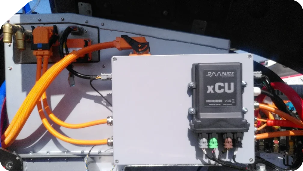
The EVParts xCU is the platform’s central controller. It manages high-voltage safety interlocks, runs motor control for the traction and auxiliary drives, reads operator input from the armrest and touchscreen, and handles thermal management.
Hardware Architecture and Pin Allocation
The xCU is built on a Texas Instruments TMS570 dual-core lockstep processor, chosen for automotive functional-safety work. It runs on a 12V or 24V vehicle supply and exposes multiple isolated CAN ports, wide-range analog inputs, contactor drivers, LIN, and Ethernet.
| Hardware Interface | Physical Specs | Protocol / Bus | Control Function |
|---|---|---|---|
| Microprocessor Core | TMS570 automotive safety CPU, dual-core lockstep | — | ISO 26262 logic execution, fault detection |
| CAN Bus Interface #1 | High-Speed CAN 2.0B, 250 kbps | SAE J1939 powertrain bus | Traction inverter, iEV & sEV drives |
| CAN Bus Interface #2 | High-Speed CAN 2.0B, 250 kbps | CANopen energy bus | Battery management system, 22 kW OBC |
| CAN Bus Interface #3 | High-Speed CAN 2.0B, 250 kbps | Body control bus | Touch display, armrest controls |
| Ethernet / LIN Port | 100Base-T1 / LIN 2.1 | Automotive Ethernet | Remote fleet telemetry, flash updates |
| High-Side Digital Drivers | Low/high-side, 12/24V, 2A | PWM relay control | Main HV contactor coils, pre-charge relay |
| Analog Input Channels | Wide-range ADC (0–5V / 0–24V) | Sensor sampling | Throttle pedal, brake pressure, temp sensors |
| Engine Emulation Interface | Configurable I/O array | Speed/load signal generation | Replaces diesel RPM signals for hydraulics |
Model-Based Design Development Toolchain
Software for the xCU is built in MATLAB/Simulink using a model-based design workflow rather than hand-coded C — this keeps the safety logic auditable and avoids a whole class of hand-coding bugs.
Phase 1: Simulink Model Architecture and Engine Emulation
The control logic lives in Stateflow state machines governing the vehicle’s operating states: Initialization, HV Pre-Charge, Drive Ready, Sweeping Active, Safe-Torque-Off, and Fault Shutdown. Engine emulation logic converts pedal position, sweeping mode selection, and hydraulic pressure feedback into torque and speed demands, sent over CAN to the A4001 and sEV inverters — the same role a diesel engine’s RPM output would have played for the hydraulics.
Phase 2: Software-in-the-Loop Verification
Before any code reaches real hardware, the control algorithms run against a digital twin of the vehicle — mass, tire traction, hydraulic pressure, fan airflow, and battery electro-thermal behavior. This is where edge cases get tested: a jammed brush, a cold-soaked battery, an emergency stop, without risking a physical unit.
Phase 3: Automatic Code Generation
Once the SIL model checks out, Embedded Coder converts it directly into C/C++, integrated with the TMS570’s low-level drivers.
Phase 4: Secure Flashing via UDS over CAN
The compiled binary is flashed over a secure UDS (ISO 14229) bootloader on the vehicle CAN bus, which also supports field updates and remote calibration.
Thermal Management and High-Voltage Safety
Putting high-voltage drives and fluid power systems into a compact utility chassis means the thermal management, electrical isolation, and functional-safety systems all have to work together, not just individually meet spec.
Thermal Management Architecture
A 50:50 water-glycol loop cools the traction inverter, the A4001 auxiliary inverters, the iEV-2U motors, the battery pack heat exchanger, and the hydraulic oil cooler, at a regulated flow rate of 12–16 L/min per motor-inverter pair and an inlet pressure of 0.5–3.0 bar. Where an sEV motor is used instead — the suction fan drive, for instance — air cooling replaces the liquid loop entirely, which simplifies plumbing and removes a source of coolant leaks near the hopper.
Both motor families are rated for -20°C to 100°C ambient. PT1000 sensors track stator winding temperature continuously: at 165°C the xCU begins derating motor current, and at 180°C it executes a soft shutdown to protect the winding insulation.
High-Voltage Distribution and Protection
The HV-PDU distributes 335V power from the battery to every high-voltage load, through three layers of protection:
- Active pre-charge. A pre-charge relay and a 100 Ω / 100 W ceramic resistor limit inrush current until the DC link reaches 95% of battery terminal voltage, at which point the main contactors close.
- High-voltage interlock loop (HVIL). A low-voltage loop runs through every HV connector and access panel. If a cable is disconnected or a cover comes off, the xCU opens the main contactors within 100 ms.
- Isolation monitoring. An insulation monitoring device continuously checks resistance between the 335V bus and chassis ground. Below 500 Ω/V, the xCU alerts the operator and starts a controlled shutdown.
| Standard / Regulation | Requirement & Scope | Implementation on Platform |
|---|---|---|
| ISO 26262 (ASIL-C/D) | Road vehicle functional safety compliance | Dual-core lockstep TMS570 microprocessor execution |
| UN ECE Regulation 100 | Electrical safety approval for EV powertrains | Isolation monitoring, manual service disconnect (MSD) |
| UN ECE Regulation 10 | Electromagnetic compatibility (EMC) testing | Shielded orange HV cables, 10 kHz switching filters |
| IP67 / IP6K9K Ingress Class | Dust and high-pressure fluid protection | Sealed connectors, IP67 motor housings |
| PM2.5 / PM10 4-Star Level | Fine particulate emission suppression | Controlled water atomization and vacuum airflow |
Synthesis and Engineering Recommendations
Electrifying a 4.8-tonne sweeper pays off mainly because the auxiliary loads get decoupled from the drive line. Running the hydraulics and the vacuum fan on their own permanent-magnet motors, instead of off one engine and a belt, is what lets the vehicle control unit throttle each system independently — that’s where the efficiency and noise gains actually come from, more so than from the traction motor itself.
Motor Supplier Assessment
Motor selection matters because it determines how much of that gain is realized in practice. iNetic Traction’s iEV and sEV product lines cover the two ends of this platform’s auxiliary needs: the iEV series brings torque density and liquid cooling for continuous, high-duty pump and fan work, while the sEV series trades some continuous power for a smaller, lighter, air-cooled package suited to weight- or space-constrained mounts. Standardized pump-flange mounting and a wide voltage range across the family (12–650 VDC) make it straightforward to swap between liquid- and air-cooled variants without redesigning the mounting interface — useful on a platform that needs both.
| Platform Feature | Baseline Diesel Drivetrain | Electrified Architecture | Operational Advantage |
|---|---|---|---|
| Primary Energy Source | Diesel ICE (Euro 6) | 335V Li-ion battery (63/100 kWh) | Zero local tailpipe emissions |
| Traction Drivetrain | Hydrostatic drive pump/motor | 88 kW electric drive + Torsen differential | Higher efficiency, regenerative braking recovery |
| Auxiliary Hydraulic Drive | Engine PTO belt/shaft drive | iEV-2U motor (33 kW) + silent pump | Independent speed regulation, >92% efficiency |
| Suction Vacuum Fan | Direct mechanical shaft engagement | sEV series (12 kW) or iEV-2U (33 kW) | On-demand power delivery; up to 46.8% weight savings with sEV |
| System Control Architecture | Distributed engine/body controllers | EVParts xCU centralized safety VCU | Model-based software design, SIL validation |
| Thermal System | Engine air radiator | Shared liquid loop + targeted air/fan cooling | Regulated cooling across inverters, battery, and motors |
Key Engineering Recommendations
- Use the sEV series where mass or packaging is the binding constraint, not power. At 17 kg with air cooling, it’s a reasonable trade against the iEV-2U’s 32 kg for jobs like a top-mounted vacuum fan, provided the continuous power requirement stays under roughly 12 kW.
- Don’t run the hydraulic pump at a fixed speed. A closed-loop control scheme on the xCU that tracks real-time manifold pressure and throttles the iEV-2U accordingly avoids wasting energy running the pump flat-out during light sweeping — one of several contributors, alongside fan-speed and traction throttling, behind the roughly 48% swing between the nominal and eco-managed shift energy modeled above.
- Mount the iEV-2U-WN400 directly on the pump housing. Its compact frame (180 × 180 × 256 mm, 32 kg) supports direct mounting, which removes a mechanical shaft, cuts structure-borne vibration, and keeps high-voltage cabling runs short.
- Set the thermal derate threshold at 165°C, not higher. That gives the xCU room to back off gradually before the 180°C hard shutdown — most useful during long summer shifts, when ambient heat is already eating into the thermal margin.
- Validate every control update against the SIL digital twin before flashing a fielded vehicle. It’s slower than pushing straight to hardware, but it catches state-machine edge cases — a jammed brush, a cold-soaked battery — that are expensive to debug in the field. The UDS bootloader means a validated update still reaches the fleet quickly.
Works Cited
- CityCat V20e – Bucher Municipal AG – PDF Catalogs | Technical Documentation | Brochure https://pdf.directindustry.com/pdf/bucher-municipal-ag/citycat-v20e/89863-1096118.html
- Bucher CityCat V20e, https://www.buchermunicipal.com/sites/default/files/2025-01_CityCat_V20e_specifications_en.pdf
- Bucher Municipal – CityCat V20e product page, https://www.buchermunicipal.com/gb/en/products/sweepers/compact-sweepers/citycat-v20e
- iPA-4U-WN400 and A4001.pdf
- iPA-2U-WN400 and A4001.pdf
- Products – iNetic Traction, https://inetictraction.com/products/
- sEV Motor Range – iNetic Traction, https://inetictraction.com/products/sev-motor-range/
- Bucher CityCat V20e Compact Sweeper – Westpark Motors, https://westparkmotors.ie/?products=citycat-v20e
- Vehicle Control Units – EV Parts, https://www.evparts.co.uk/vehicle-control-units/
- Elevate Performance in a Compact Package – iNetic Traction, https://inetictraction.com/wp-content/uploads/2024/02/sEV-Motor-Range.pdf
